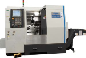
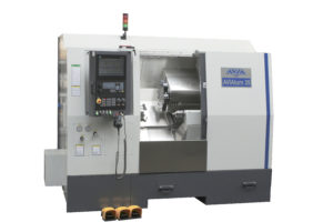
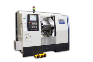
| Technical Data |
AVIAturn 35 |
AVIAturn 35M / AVIAturn 35MY |
AVIAturn 35SM / AVIAturn 35SMY |
|
|
|
|
|
| WORKING AREA: |
|
|
|
|
| Swing over bed covers |
mm |
560 |
560 |
560 |
| Max. turning diameter over cross carriage |
mm |
350 |
350 |
350 |
| Max. turning length |
mm |
600 |
580 |
580 |
| Max. bar capacity |
mm |
65 |
65 |
65 |
|
|
|
|
|
| HEADSTOCK: |
|
|
|
SPINDLE |
SUB-SPINDLE |
| Spindle nose |
type |
A2-6 |
A2-6 |
A2-6 |
A2-5 |
| Max. spindle speed |
rpm |
5000 |
5000 |
5000 |
6000 |
| 3-jaw chuck diameter |
mm |
210 |
210 |
210 |
169 |
| Spindle bore |
mm |
75,5 |
75,5 |
75,5 |
– |
| Spindle motor power S1/S3(25%)* |
kW |
11/15 |
11/15 |
11/15 |
7,5/11 |
| Spindle torque S1/S3(25%)* |
Nm |
126/171 |
126/171 |
126/171 |
45/60 |
|
|
|
|
|
| AXES: |
|
|
|
|
| Travel in X axis |
mm |
-10/210 |
-60/180 (M) -55/185 (MY) |
-10/180 (SM) -10/-185 (SMY) |
| Travel in Z / Z2 axis |
mm |
610 / – |
600 / – |
600 / 520 (Z2) |
| Travel in Y axis (MY and SMY models) |
mm |
– |
±50 |
±50 (SMY) |
| Rapid traverse X / Z / X1 / Z2 |
m/min |
25/30/- / – |
25/30/- / – (M) 25/30/11 / – (MY) |
25/30/ – / 30 (SM) 25 / 30 /11/ 30 (SMY) |
|
|
|
|
|
| TURRET: |
|
|
|
|
| No. of stations / live tooling stations |
pcs |
12/- |
12/12 |
12/12 |
| Tool disc std. / option |
type |
VDI 30 / BMT 55 |
VDI 30 / BMT 55 |
VDI 30 / BMT 55 |
| Tool shank |
mm |
20 x 20 |
20 x 20 |
20 x 20 |
| Max. boring bar diameter |
mm |
32 |
32 |
32 |
| Max. driven tools speed SIEMENS / FANUC |
rpm |
– |
5000 / 5000 |
5000 / 5000 |
| Power of driven tools motor SIEMENS / FANUC |
KW |
– |
4,8/2,2 |
4,8/2,2 |
| Torque of driven tools motor S1 SIEMENS / FANUC |
Nm |
– |
11,5/11 |
11,5/11 |
|
|
|
|
|
| TAILSTOCK: |
|
|
|
|
| Travel |
mm |
500 |
500 |
– |
| Max. axial thrust |
N |
5000 |
5000 |
– |
| Centre seat |
MK |
5 |
5 |
– |
| Tailstock travel execution |
|
hydraulic cylinder |
hydraulic cylinder |
– |
|
|
|
|
|
| CNC CONTROLS: |
|
|
|
|
| FANUC (standard) |
type |
0i-TF |
0i-TF |
0i-TF |
| SIEMENS (option) |
type |
SINUMERIK 828D |
SINUMERIK 828D |
SINUMERIK 828D |
|
|
|
|
|
| GENERAL DATA: |
|
|
|
|
| Dimensions: L x W x H without chip conveyor |
mm |
2860x1660x2120 |
2860x1660x2120 |
2860x1660x2120 |
| Weight c.a. |
kg |
3850 |
3850 |
4000 |
| Total power installed* |
kVA |
c.a. 24 |
c.a. 26/29 |
c.a. 38/40 |
| *for FANUC 0i-TF |
|
|
|
|
| STANDARD: |
- digital package of servo-drives for axes and spindle,
- 12-station servo turret VDI 30,
- self-centering, Ø210 mm 3-jaw chuck with hydraulic clamping,
- sets of hard and soft jaws for 3-jaw chuck,
- through hole chuck cylinder,
- linear guideways in X / Z axes,
- telescopic guideways covers made of stainless steel,
- ball screws with double preloaded nut,
|
- automatic lubrication system for ball screws and guideways,
- coolant system with coolant supply through tooling disc,
- electronic handwheel,
- fully enclosed working area with lighting installation,
- Ethernet, PCMCIA, RS 232, USB (SIEMENS only),
- operating and programming manuals.
|
| OPTIONS: |
- hydraulic tailstock,
- tool probe,
- chip conveyor,
- additional soft jaws for the chuck,
- collet chuck with collets,
- cut-off parts catcher with container,
- self-centering, Ø250 mm 3-jaw chuck with hydraulic clamping
|
- bar feed system,
- oil mist collector,
- oil separator,
- toolholders,
- CAD/CAM software,
- coolant gun for working area cleaning,
- other upon request.
|


